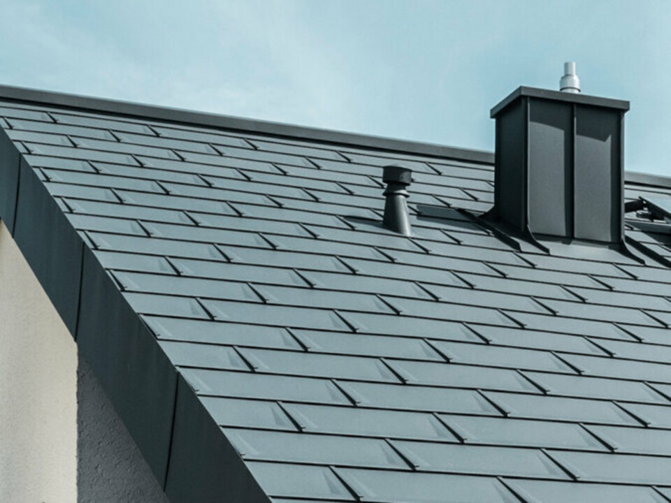
Installation guidelines
Please select one or more chapters to download.
Table of contents

Installation of PREFALZ solar panel

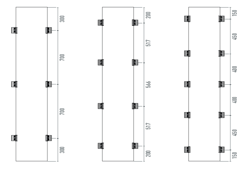
The sketch shows three different variants for installing the PREFALZ solar panel with 6, 8 or 10 fastening points. The diagram indicates the distance at which the clamps are to be mounted depending on the required variant.

Note

The variant to be used depends on local conditions as well as wind and snow loads. For this purpose, PREFA provides a calculation tool, which can be requested via the website or at office.uk@prefa.com via the Product Technology department.

  • The maximum centre-to-centre spacing between clips must not exceed 33 cm (Fig. 1).
  • Care must be taken to ensure that the substrate is clean in the clamp area. Due to the symmetrical clamping jaws, any positioning on the fold is possible (Image 2).
  • Position and linear alignment of the clamp bases according to the required number depending on the static design according to the installation plan (Image 3).
  • Tighten the two stainless steel nuts with a torque of 35 Nm. Care must always be taken to tighten the left nut first to prevent the clamp from tilting upwards (Image 4).
  • Insertion of the solar panels and connection of the connectors according to string planning. Care must be taken to ensure that the solar panels are positioned centrally on the clamp bases and that the EPDM inserts fit properly (Image 5).
  • Connection of the solar plugs/sockets (Image 6). 
  • Position the clamp tops and tighten the hexagon socket screws with a torque of 10 Nm (Fig. 7).
  • Place the solar panel safety locks along the lower panel edge of each row and tighten the hexagon socket screws with 10 Nm (Fig. 8).
  • A snow guard system can be arranged above the solar panels to protect the cabling (Image 9). The snow guard system of the entire roof surface must be considered separately!
  • The equipotential bonding cable must be installed for each continuous roof surface (Fig. 10).